Setting Up a Pattern Projector with the Bumblebee X Camera
Overview
For low texture indoor scenes, a random dot pattern projector is available as an optional accessory. This application note contains information on how to use the Smart Vision Light pattern projector with the Bumblebee X camera as well as the wiring and configuration details.
The pattern projector can be mounted on top or the bottom of the camera using a bracket. It can be connected to the camera via GPIO for synchronization.
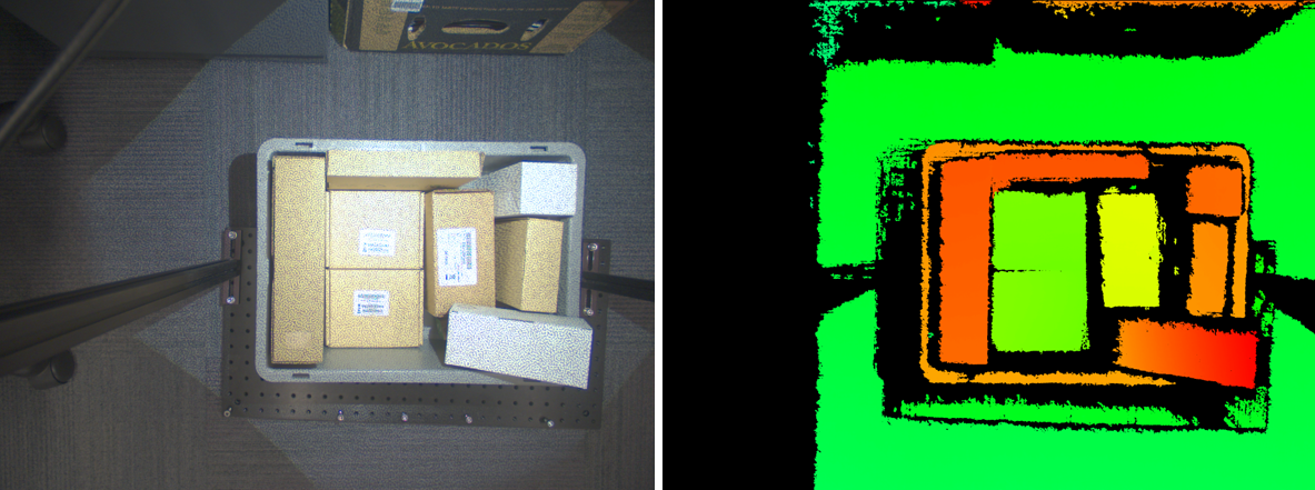
With the pattern projector synchronized to the camera, here is a sample left rectified image and its corresponding disparity image:
Jump to: Mounting | Lens | Modes | Wiring Guides | SpinView Setup
Pattern Projector Kits
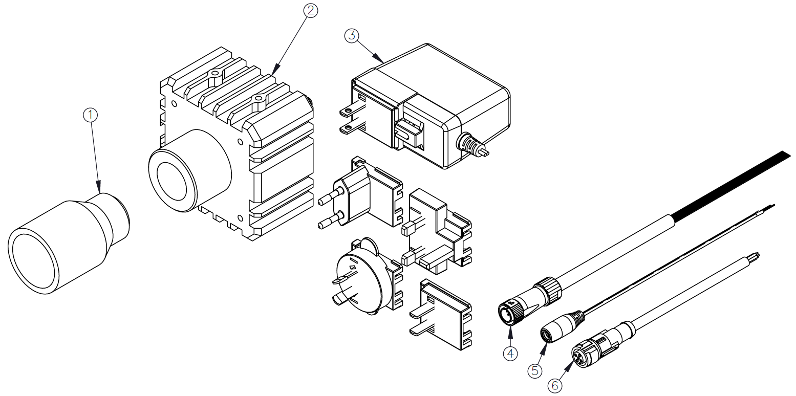
Teledyne FLIR offers the KIT-SXP80G2-WHI pattern projector kit for the color Bumblebee X cameras. The kit and contents are shown below.
| Item Number | Part Number |
Item | Description |
| 1 | 4255579 | Lens | Vari-Focal, C-mount, AZURE IR02812ZM |
| 2 | 4255615 | Smart Vision Light | SXP80G2-WHI White Light Projector with Reticle |
| 3 | 4255614 | Power Supply | 24 V 1.5 A, AC/DC, Global, Wall mount |
| 4 | ACC-01-3017 | GPIO Cable for Bumblebee X camera | Hirose LF10WBP-12 to Wire Leads, 3 m |
| 5 | 4255647 | Power Cable | DC Jack 2.1 mm to Leads, 1 m |
| 6 | 4255646 | GPIO Cable for Projector | M12 5 Pin A-coded to Wire Leads, 5 m |
Mounting the Pattern Projector
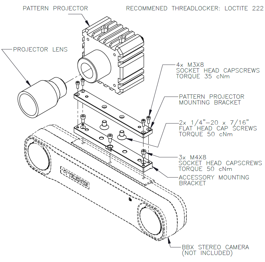
The mounting bracket needed depends on the Bumblebee X model.
- For the BX-P5G-30C/M-XC3 and BX-P5G-30C/M-XC5 (60° and 80°) models, use the ACC-03-0001 bracket kit.
- For the BX-P5G-30C/M-XC7 (105°) models, use the ACC-03-0002 bracket kit.
BX-P5G-30C/M-XC3 and BX-P5G-30C/M-XC5 (60° and 80°) Models
To mount the pattern projector to the BX-P5G-30C/M-XC3 and BX-P5G-30C/M-XC5 Bumblebee X cameras:
|

|
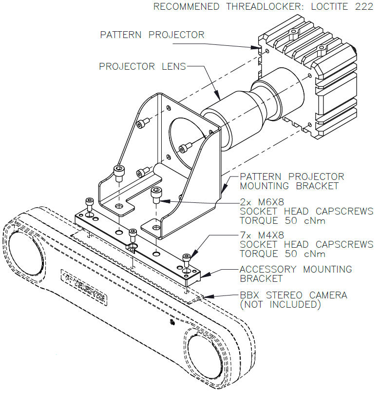
BX-P5G-30C/M-XC7 (105°) Models
To mount the pattern projector to the BX-P5G-30C/M-XC7 Bumblebee X cameras:
- Attach the pattern projector mounting bracket to the front of the pattern projector with four of the M4X8 socket head screws.
- Attach the second bracket to the Bumblebee X camera with the remaining three M4X8 socket head screws. This bracket can be attached to the top or the bottom of the camera.
- Attach both brackets together with the two M6X8 socket head screws.
Attaching a Lens
You must attach a C-mount lens to the pattern projector.
|

|
Modes of Operation
The projector has two operation modes: Continuous and Overdrive, where the Overdrive mode draws higher current to provide higher intensity. See below for the different wiring configurations.
| Continuous Operation | Overdrive Operation | |
|---|---|---|
| Electrical Input | 24 VDC +/- 5% | |
| Input Current | Maximum 840 mA | Peak 1.25 A during strobe |
| Input Power | Maximum 20 W | Peak 30 W during strobe |
| PNP Trigger | 2 mA at 5 VDC | 8 mA at 10 VDC | 15.4 mA at 24 VDC | |
| NPN Trigger | 12.5 mA at Common (0 VDC) | |
| Trigger Input | PNP > +4 VDC (24 VDC maximum) to activate or NPN ≥ 1 VDC to activate (not both) | |
| Mode Control | Connect pin 5 to 1-10 VDC (10 - 100% output); 24 VDC maximum | Connect pin 5 to GND (see wiring configuration) |
| Strobe Duration | Minimum 10 μs | Maximum ∞ | Minimum 10 μs | Maximum 50 ms |
| Strobe Frequency | Maximum 4 kHz or 1 / Duty Cycle as calculated, whichever is less | |
| Strobe Trigger Latency | 6 μs | |
| Duty Cycle | Not Applicable | Maximum 10% |
| Power Indicator | Green when powered up | |
| Status Indicator | Amber when on | Red when a fault is detected | |
| Analog Intensity | Output adjustable from 10 - 100% of intensity limit by a 1 - 10 VDC signal. Jumpering pin 5 to pin 1 provides maximum intensity. |
|
| Connection | 5-pin M12 connector | |
| Operating Temperature | -10° to 40° C (14° to 104° F) | RH maximum 80% non-condensing humidity | |
| Storage Temperature | -20° to 70° C (-4° to 158° F) | RH maximum 80% non-condensing humidity | |
| IP Rating | IP50 | |
| Mass | ~580 grams | |
| Compliance | CE, IEC 62471, RoHS | |
| Warranty | 3 years | |
Wiring Guides
| See a short video on how to connect cables between the pattern projector and Bumblebee X camera. |

|
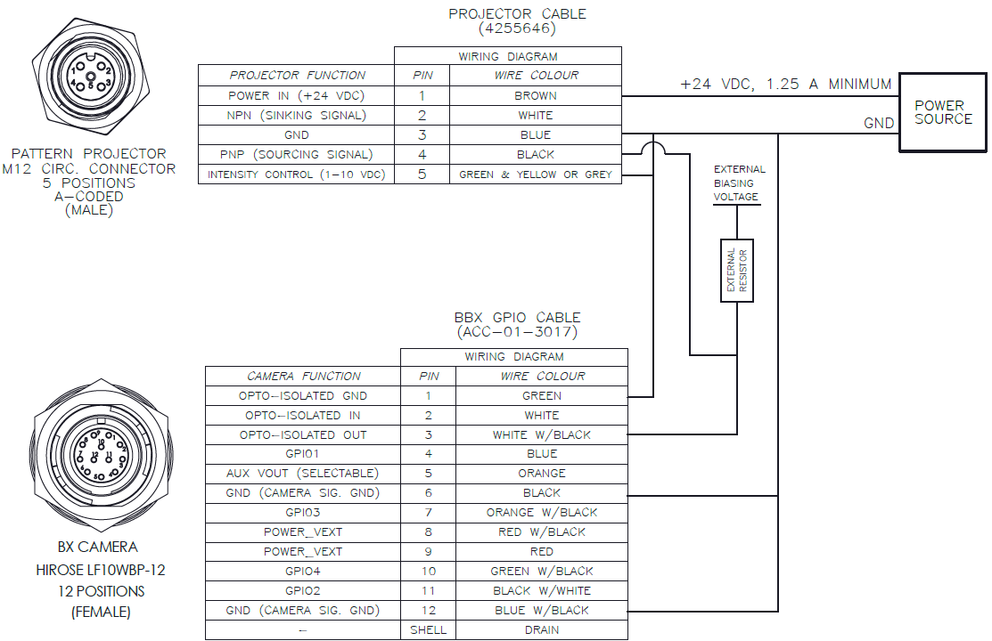
Continuous Mode
The following wiring schematic illustrates how to connect the camera to the projector in continuous mode.
Note: Power requirements are different between continuous and overdrive operations modes.
To use continuous mode, either:
Tie Projector Pin 4 (PNP)-->Projector Pin 1 (Power In)
OR
Tie Projector Pin 2 (NPN)-->Projector Pin 3 (GND)
Do NOT do both.
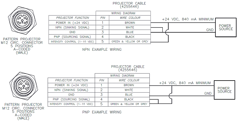
| For Variable Intensity | For Maximum Intensity | |
| Tie Projector Pin 5 (Intensity Control) to Bumblebee X Pin 5 (Aux Vout) or to any voltage source | Tie Projector Pin 5 (Intensity Control) to Projector Pin 1 (Power In) |
Note: An external resistor is not required to pull the voltage line when using the projector’s NPN line. It is needed for wiring up the PNP line in the later examples.
NPN - Overdrive Mode
The following wiring schematic illustrates how to connect the camera to the projector in overdrive mode using the NPN line. This example shows the projector being triggered by the camera via the camera's opto-isolated output. The projector can be externally triggered by other devices as well.
Note: Power requirements are different between continuous and overdrive operations modes.
For overdrive mode:
- Tie Projector Pin 5 (Intensity Control) to Projector Pin 3 (GND).
There is no intensity adjustment because of this.
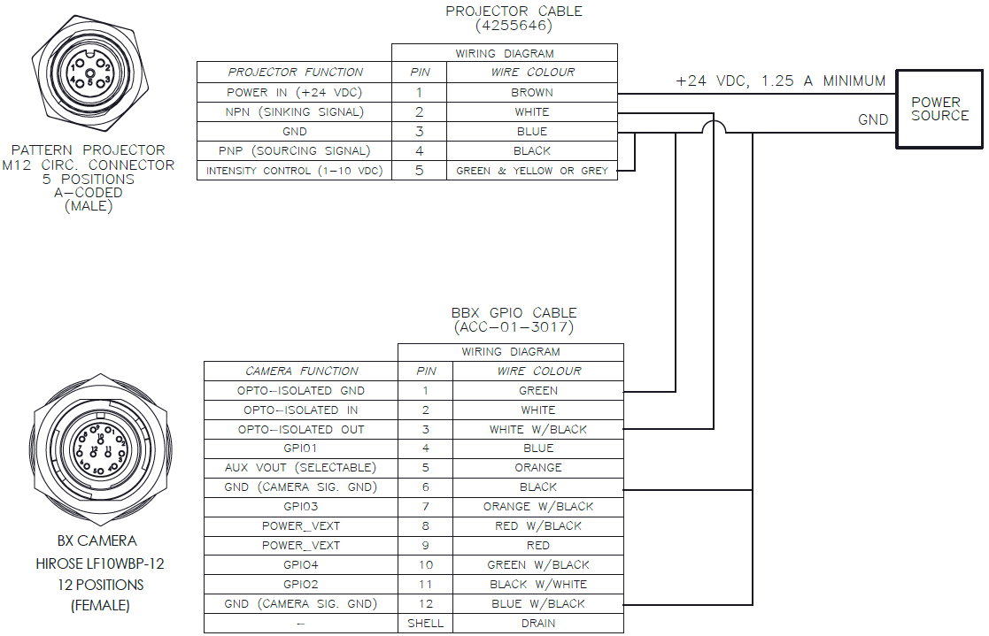
Notes:
- No external resistor is required.
- The logic on the Output pin of the camera needs to be inverted so that it functions like a PNP.
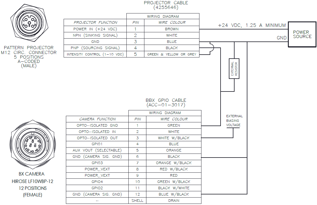
PNP - Overdrive Mode Example 1
The following wiring schematic illustrates one example of how to connect the camera to the projector in overdrive mode using the PNP line.
Notes:
An external resistor must be used to drive the PNP line on the device. The selection of the external resistor value influences the timing (changing the resistor value changes the time constant of the RLC circuit).
Reference resistor values and minimum external bias voltages necessary to drive the projector:
- 4k7 OHM - 9 VDC
- 1k OHM - 5 VDC
- 330 OHM - 4 VDC
Do not exceed 24 VDC for the external bias voltage. Higher voltages will cause damage to the camera.
The line does not need to be inverted in SpinView.
The downside of this setup is that the minimum voltage required to drive the projector depends on the value of the external resistor.
PNP - Overdrive Mode Example 2
The following wiring schematic illustrates another example on how to connect the camera to the projector in overdrive mode using the PNP line.
Notes:
An external resistor must be used to drive the PNP line on the device. The selection of the external resistor value influences the timing (changing the resistor value changes the time constant of the RLC circuit).
Reference resistor values and minimum external bias voltages necessary to drive the projector:
- 4k7 OHM - 3.2 VDC
- 1k OHM - 3.5 VDC
- 330 OHM - 4.0 VDC
Do not exceed 24 VDC for the external bias voltage. Higher voltages will cause damage to the camera.
The logic on the Output pin of the camera needs to be inverted so that the PNP line functions properly.
The upside of this setup is that a very low minimum voltage is required to drive the projector and it is dependent on the value of the external resistor used.
Configuring SpinView to Trigger the Projector
There are two ways to trigger the projector with SpinView:
- Syncing the projector output by tying the pulses with the frame rate.
- Using a counter at a higher pulse rate of the frame.
Synching the output with the Frame Rate
The simplest way is to tie the projector’s pulse with the frame rate resulting in the camera capturing the light output.
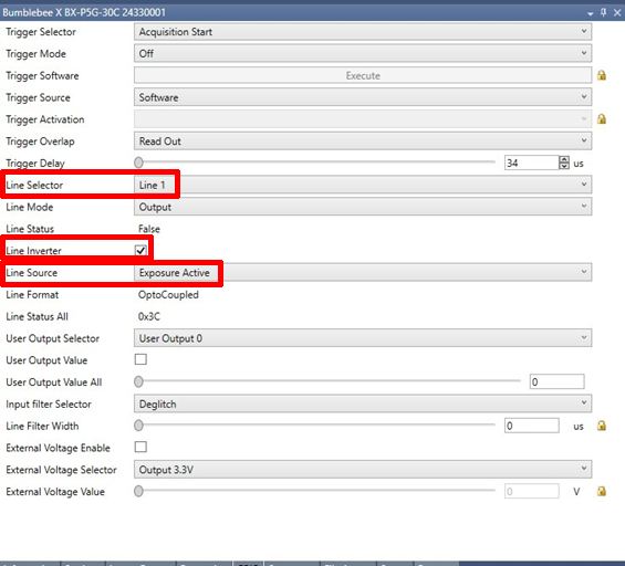
|
1. Under GPIO settings: a. Set Line Selector to the Opto-Out (Line 1 for camera). b. Set the Line Mode to Output. c. Select Line Inverter for NPN setup or PNP Overdrive Example 2 setup. d. Set Line Source to Exposure Active. |

|
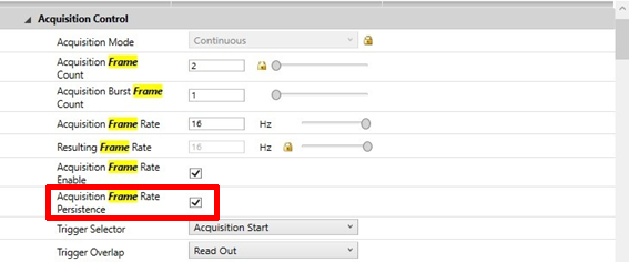
2. Under Acquisition Control:
- Enable Acquisition Frame Rate Persistence.
3. Under Settings:
- Adjust the frame rate. Start low to allow projector to catch up with the frame. Slowly adjust while observing the image to check that projector light is seen and steady.
Using the Counter
A counter can also be used to drive the pattern projector. The counter allows you to adjust the pulse rate of the camera.
1. Under GPIO settings:
a. Set Line Selector to the Opto-Out (Line 1 for camera).
b. Select Line Inverter for NPN setup or PNP Overdrive Example 2 setup.
c. Set Line Source to Counter 0 Active.
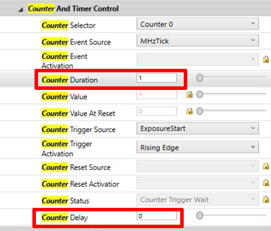
2. Under Counter and Timer Controls:
- Both counter duration and counter delay control the pulse width of the projector. You can leave the counter delay to 0 and adjust the counter duration only.
Note that if the line is inverted, a lower counter duration corresponds to a shorter pulse width, otherwise a higher counter duration corresponds to a shorter pulse width.