Configuring Stereo Parameters for the Bumblebee X Camera
This application note describes some of the parameters used to configure the Bumblebee X stereo camera.
Using SpinView to Configure the Bumblebee X Camera
Most of the settings described in this application note are accessible from the Stereo or Features tab in the SpinView application.
In SpinView, click on the camera model to access the settings.
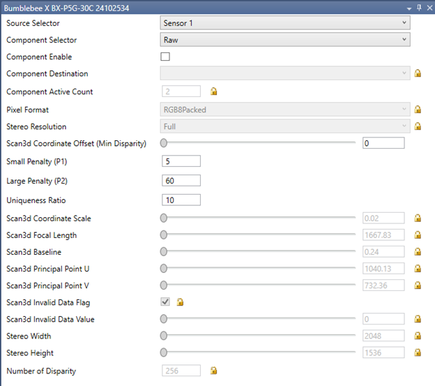
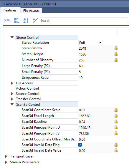
| Windows - click the stereo tab to see the parameters | Linux - click the Features tab to see the parameters |
 |
 |
Configuring Streams
Components
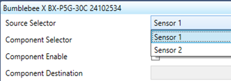
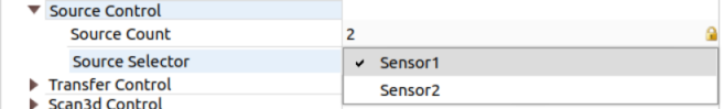
1. From the Source Selector, select the source, either Sensor 1 (Left) or Sensor 2 (Right).
| Windows | Linux |
 |
 |
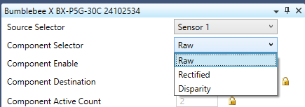
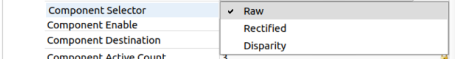
2. From the Component Selector, select the component: either Raw, Rectified, or Disparity for Sensor 1 or either Raw or Rectified for Sensor 2.
| Windows | Linux |
 |
 |
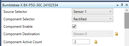
3. Click Component Enable to enable the selected component.
| Windows | Linux |
 |
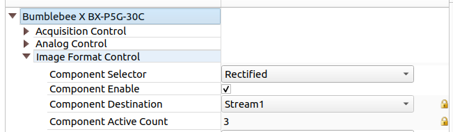 |
Component Destination indicates the component destination stream. This updates as more components are enabled. The Component Active Count indicates the number of components that have been activated. Activate the components you need in the image transmission and then observe each components destination to determine which stream is assigned to which component before entering acquisition mode.
Pixel Formats
![]()
For color cameras, raw and rectified images are output in RGB8Packed by default, but can be output in YUV422Packed format, reducing the bytes required by 33% from the standard RGB8Packed format. This allows for a higher frame rate at the same resolution. The disparity image is unaffected. Raw and rectified images can be output in RGB12 format which has higher bit depth but slower frame rate due to the additional bandwidth required. The pixel format selection applies to raw left, raw right, rectified left, and rectified right images; any pixel format change affects all 4 streams.
For mono cameras, raw and rectified images are output in Mono8 by default, but can be output in Mono12Packed format which has higher bit depth but slower frame rate due to the additional bandwidth required.
| For examples see the instructional video |
|
Configuring Stereo Resolution
Stereo Resolution Selects the resolution output of the stereo engine. Stereo resolution can be viewed through Stereo Width and Stereo Height.
Stereo resolution only refers to the rectified and disparity images. Raw images remain at full resolution.
The Bumblebee X XC3 60° and XC5 80° FOV models have a 4:3 aspect ratio. Full resolution is 2048 x 1536 and Quarter resolution is 1024 x 768.
The Bumblebee X XC7 105° FOV models have a 16:9 aspect ratio. Full resolution is 2048 x 1152 and Quarter resolution is 1024 x 576.
Higher resolution yields more details and better disparity precision but requires more processing power. For applications that demand faster performance, quarter resolution may be the preferred option.
| For examples see the instructional video |
|
Configuring Noise Reduction Parameters
There are several parameters that can affect the noise of the image.
| Parameter | Description | Possible Values |
Recommended Value |
| Uniqueness Ratio | The margin by which the best cost must win over the next best to be considered valid. Increasing this ratio removes noisy points, resulting in fewer 3D points. | 0 - 100 | 10 |
| Maximum Speckle Size | Maximum size of disparity region to consider their noise speckles and invalidate | 1 - N/A | 40 |
| Speckle Threshold | Maximum disparity variation allowed within a connected component during speckle filtering | 0 - 255 | 4 |
| For examples see the instructional video |
|
Configuring Minimum Disparity
Minimum disparity is configured using the Scan 3D Coordinate Offset parameter. This is the offset when transforming a pixel from relative coordinates to world coordinates. It is equivalent to minimum disparity. It can be set within a range of 0 to 768. Use a lower value for objects further from the camera. Use a higher value for objects nearer to the camera.
| For examples see the instructional video |
|
Configuring Stereo Penalties
Small Penalty (P1) is the penalty for disparity changes of 1 pixel between neighbor pixels. Decreasing this parameter helps with slanted surfaces where the depth changes quite slowly. It can be set within a range of 1 to 255. The default is 5. Lower P1 allows smoother depth transitions while higher P1 reduces sensitivity to minor shifts.
Large Penalty (P2) is the penalty for disparity changes greater than 1 pixel between neighbor pixels. Decreasing this parameter helps when the depth changes abrupty like edges of objects against a background. Large Penalty should be larger than Small Penalty. It can be set within a range of 1 to 255. The default is 60. Higher P2 prevents large disparity jumps, minimizing the noise but smoothing out sharp edges.
| For examples see the instructional video |

|